12V Solar Panel Wiring Diagram With Inverter: Step-by-Step Guide
Lay the main parts of a small 12V solar system on a bench and the route is fairly obvious. The panel connects to the charge controller, the controller looks after the battery, and the inverter draws from that battery when you need 120V power at an outlet.
Where people get caught out is the battery side. Do not mistake that low voltage for a low-energy source. Drop a metal tool across the terminals or let a poor connection heat up, and the battery can damage wiring very quickly. This page shows the power path; the equipment manuals tell you which cable, fuse, settings, and terminal hardware belong in the build. Once that build ties into an RV or a building, bring in an installer who knows the wiring rules that apply there.
What Does a 12V Solar Panel Wiring Diagram With an Inverter Look Like?
In a 12V solar panel wiring diagram, the power path for a small off-grid system usually looks like this:
Solar panel(s) → PV disconnect or protection → charge controller → 12V battery bank → inverter fuse and disconnect → inverter → AC loads
That line shows the direction of energy flow, not every conductor or safety device. The controller and inverter normally have separate connections to the battery or to properly rated positive and negative busbars. The inverter does not take its power from the controller’s small-load output.
Main Components in the Diagram
Four parts do most of the work:
Solar panel(s): Produce DC electricity. A “12V nominal” panel often has an open-circuit voltage around 18V to 22V, although its label is the authority.
Charge controller: Regulates array power so the battery receives the right charging profile. PWM and MPPT models have different input limits.
12V battery bank: Stores energy for later use. LiFePO4, AGM, and gel batteries require different settings and have different operating limits.
Inverter: Draws DC power from the battery and supplies AC power. Pure-sine-wave output is generally preferred for motors and sensitive electronics.
Component | What It Does | Typical Input | Typical Output |
Solar Panel | Produces unregulated DC power | Sunlight | Often about 18V-22V open circuit for a nominal 12V panel |
Charge Controller | Manages battery charging | PV voltage within the controller’s stated range | Charging voltage selected for the battery chemistry |
12V Battery | Stores energy and supplies high DC | Output from the charge controller | Voltage that changes with chemistry, charge, and load |
Inverter | Converts battery power to AC | A model-specific 12V DC range | Usually 120V AC in a U.S. system |
These are orientation figures only. Cold-weather panel voltage must remain below the controller’s limit, and the charging profile must match the solar battery. “12V” is a system name, not a promise that every point sits at 12.0 volts.
DC and AC Sections in the Diagram
From the panels through the battery, the system is carrying DC. Follow the cables as far as the inverter input and that is still true; the familiar 120V AC appears at the inverter output. That is why a spare breaker from a household panel is not automatically suitable on the solar or battery side. It needs a DC rating for the job.
At 12V, producing useful power takes a lot of amperage. A 1,200W output works out to about 100 amps in perfect arithmetic, and the real battery draw will be higher after conversion losses. It may rise again as battery voltage falls. This is why the short pair of cables between the battery and inverter is often much heavier than the panel wiring.
Using the receptacles built into an inverter is one thing. Connecting its output to an RV panel, subpanel, or household circuit is another. At that point, grounding, neutral bonding, transfer equipment, and local electrical rules all come into play, and the simple diagram on this page is no longer enough by itself. A detailed solar panel wiring diagram can help distinguish portable DC wiring from fixed AC connections.
Polarity and Wire Markings
Cable color is useful, but it is not proof. Most 12V installations use red for positive and black for negative, although inherited wiring has a way of producing surprises. Read the positive and negative marks at the equipment, then check them with a multimeter before attaching the cable.
On a typical U.S. AC circuit, expect black for hot, white for neutral, and green or bare copper or green for the equipment ground. Treat those colors as a cross-check, not as the instruction sheet. The inverter diagram will show how that particular model handles the neutral and ground.
Label both ends of every cable before the bundle becomes crowded. It takes a minute during assembly and saves a great deal of tracing later.
How Do You Wire a 12V Solar Panel System With an Inverter?
First, isolate every source. Open the battery and PV disconnects, switch the inverter off, and keep the panels covered. Because panels produce voltage in light, a cover is not a substitute for a rated disconnect and meter check.
The sequence below is common, not universal. If the instructions supplied with your controller or inverter call for a different order, follow them.
Step 1: Connect the Battery to the Charge Controller
Many controllers need to see the battery before the array so they can identify system voltage and load the right settings. Select the correct battery chemistry and charging values before continuing.
Run correctly sized copper conductors between the battery and controller. Protect the positive conductor near the battery with a DC-rated fuse or breaker selected for both the equipment and cable.
Tighten terminals to the manufacturer’s torque specification rather than judging them by feel. A connection can look secure and still develop resistance, heat, and voltage drop under load.
Step 2: Connect the Solar Panel to the Charge Controller
Before closing the PV disconnect, confirm that the series and parallel arrangement stays within the controller’s voltage and current limits. Allow for open-circuit voltage to rise in cold weather.
Route the conductors through any required PV-rated disconnect, breaker, fuse, or combiner, then connect the controller’s PV input. Protect cables from abrasion, and do not substitute ordinary AC-only devices for solar DC equipment.
After checking the terminations, close the disconnect or uncover the panels in the specified order. A full battery may accept little current, so a low charging figure is not automatically a fault.
Step 3: Connect the Battery to the Inverter
The inverter belongs on the battery bank or on busbars designed for the expected current. Do not connect it to the charge controller’s load terminals unless the controller manufacturer specifically approves that inverter and load. Those terminals are commonly meant for modest DC loads and can be damaged by inverter current or startup surge.
Keep both inverter cables short and use the same conductor size for positive and negative. Fit the specified DC fuse and disconnect near the battery. The fuse must protect the cable and have enough DC interrupting capacity for the battery bank, especially with lithium batteries.
Make the connection with the inverter off. Use the manufacturer’s pre-charge procedure where one is specified, and remove jewelry before working near exposed battery terminals.
Step 4: Connect the Inverter to AC Loads
With covers in place and the DC wiring checked, start the inverter without a load. Confirm normal output, then try a small appliance before the largest planned load.
Devices can plug directly into built-in inverter outlets when that is how the product is designed to be used. Keep the loads there unless the system was purpose-built to supply fixed wiring. Running a cord from the inverter into a wall receptacle creates a backfeed path and can put voltage on wiring that someone else expects to be dead.
Supplying a transfer switch, RV panel, subpanel, or branch circuit calls for listed connection equipment and a neutral-and-ground arrangement that matches the inverter. Once the output leaves the built-in receptacles, this is no longer a simple portable setup. Have a qualified electrician handle that part of the design and installation.
What Should You Check Before Operating the System?
Before trying a full load, stop and take one slow pass through the installation with the sources isolated. Confirm the polarity and terminal torque, then trace each cable from end to end. It should be supported, protected by the correct fuse, and clear of sharp edges or hot surfaces. Finish by checking the controller’s battery profile and making sure air can move freely around the inverter and controller.
Verify Battery and Panel Voltage
Measure panel polarity and open-circuit voltage at the PV disconnect, then compare the result with the label and array plan. Remember that open-circuit voltage can be higher in cold weather.
Next, measure the battery directly at its terminals. A rested, fully charged lead-acid battery often reads about 12.6V to 12.8V. A 12V LiFePO4 battery may show roughly 13.3V to 13.6V near the upper part of its charge range, but its voltage curve is quite flat. One voltage reading is therefore a poor way to estimate lithium state of charge. The battery monitor or BMS and the manufacturer’s chart are more useful.
Repeat the measurement at the inverter while a load runs. A large difference points to cable or connection resistance.
Confirm Your Inverter Can Handle Your Loads
List the equipment that may run at the same time and add its normal wattage. Remember that the inverter also uses some power of its own. Give the total a sensible margin instead of building a plan around the inverter’s absolute limit, and make sure the battery’s continuous-discharge rating and BMS limit are high enough for the resulting DC current.
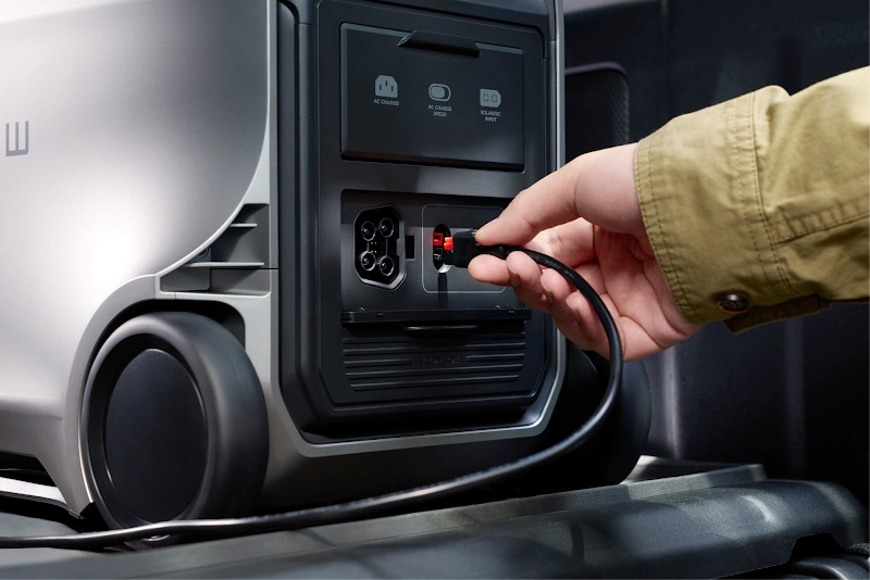
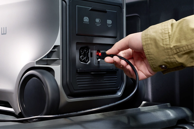
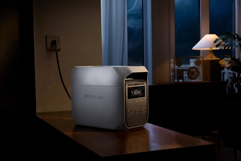
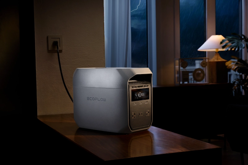
If you would rather avoid matching a separate battery and inverter yourself, an all-in-one power station can simplify the setup. The EcoFlow DELTA 3 Classic Portable Power Station (1024Wh), for instance, combines a 1,024Wh battery with 1,800W of AC output in one unit. That gives you enough room to cover common backup needs such as lights, internet equipment, laptops, TVs, and other everyday essentials without building a full 12V system from individual components.
Verify Your Inverter Handles Startup Surge
A refrigerator, pump, compressor, or tool can briefly demand far more than its running wattage. Use label data or a measured startup value rather than guessing.
Surge ratings have time limits. The battery, BMS, fuse, connections, and cables must all carry that demand without excessive voltage drop.
For homes that need to run more demanding appliances, the EcoFlow DELTA 3 Ultra Plus Portable Power Station (3072Wh) offers 3,600W of AC output and up to 7,200W of surge power. The higher surge capacity is particularly useful when equipment needs a strong burst of power at startup. It also provides a more straightforward option for users who need higher output but do not want to size and wire a separate battery bank, inverter, and protection system themselves.
Check Wire Sizes and Overcurrent Protection
Cable size depends on minimum battery voltage, inverter efficiency, run length, voltage drop, insulation rating, heat, and installation method—not wattage alone. Use the inverter manual plus proper ampacity and voltage-drop calculations.
The figures below are rough planning examples for a 12V system with a very short copper run. They do not replace the manufacturer’s cable and fuse table. A wiring diagram for solar is only a planning aid; the equipment manual still governs cable and fuse selection.
Inverter Continuous Power | Continuous DC Current (at 12V) | Recommended Minimum Wire Gauge (≤5 ft) | Recommended Fuse Size |
500W | About 45A–55A | 8 AWG – 6 AWG | About 60A |
1000W | About 90A–110A | 4 AWG – 2 AWG | About 125A–150A |
1500W | About 135A–165A | 2 AWG – 1/0 AWG | About 175A–200A |
2000W | About 180A–200A | 1/0 AWG – 2/0 AWG | About 250A–300A |
Do not automatically pair a cable with the largest fuse shown. The fuse must be no larger than the conductor and connected equipment can safely tolerate, while still allowing the inverter’s expected operating and surge current. Use a fuse and holder that are DC-rated and appropriate for the battery’s available fault current.
Follow Applicable U.S. Electrical Requirements
A fixed installation can touch several parts of the National Electrical Code (NEC) at once. Article 690 addresses the PV portion, Article 706 covers energy storage, and Article 710 applies to stand-alone systems. Article 705 may also enter the picture when a source operates in parallel with utility power. RV, marine, and locally adopted rules may add another layer.
Do not simply attach every negative terminal and case to the nearest rod or chassis. The right grounding and bonding arrangement depends on the inverter, DC topology, neutral, and transfer equipment. Have fixed AC wiring checked by a qualified professional.
What Are Common 12V Solar Wiring Problems?
If the system misbehaves, isolate it in the manufacturer’s sequence and begin with meter readings instead of replacing parts at random.
The Inverter Does Not Turn On
Confirm that the battery disconnect is closed, the BMS is awake, and voltage at the inverter is within range. With power isolated, test the external fuse; it can look intact and still be open.
If voltage is healthy at the posts but low at the inverter, inspect the lugs, switch, fuse holder, and cable. After reversed polarity, stop and follow the maker’s service instructions.
The Battery Is Not Charging
Check the controller’s status and error history, battery voltage, and chemistry setting. Measure at its battery terminals as well; an open fuse or disconnect may not be obvious from the display.
The array must be above the startup threshold and below the maximum PV input. If connection order may be the issue, shut down and restart exactly as the manual directs.
Solar Panel Output Is Too Low
A panel’s nameplate wattage comes from standard test conditions. Clouds, haze, sun angle, hot cells, and controller limits all reduce real output.
Check for shadows from vents, antennas, racks, leaves, or branches. Dirt also matters, especially on shallow-mounted panels.
If sunlight is good, inspect connectors and measure along the circuit. Heat, browned insulation, or inconsistent readings suggest a bad connection. Do not unplug ordinary PV connectors under load.
The Inverter Shuts Down Under Load
Watch inverter input voltage as the appliance starts. A sharp drop points toward the battery, BMS, cables, lugs, or fuse holder.
If voltage stays in range, compare startup demand with the surge rating and duration, then check temperature and airflow. Remove loads one at a time and retest. Repeated trips call for diagnosis, not a larger fuse.
Conclusion
A useful 12V solar diagram begins with the panels, passes through a charge controller to the battery, and ends at an inverter that supplies the AC load. The part worth slowing down for is everything the single line leaves out: disconnects, fuses, conductor size, polarity, terminal torque, battery settings, grounding, and startup current.
Connect equipment in the sequence given by its manufacturer, verify polarity with a meter, and protect each conductor for the current it can safely carry. Keep the inverter on its own properly protected battery connection, never backfeed a wall outlet, and bring in a qualified installer when the AC output becomes part of permanent wiring. Those checks take longer than copying a generic diagram, but they are what turn the diagram into a system that works safely.
FAQ
Can You Hook a Solar Panel Directly to an Inverter?
No, you cannot connect a standard solar panel directly to a typical off-grid battery inverter. Standard 12V inverters require stable, high-current DC voltage sourced from a battery or regulated power supply, whereas raw solar panel voltage fluctuates constantly with passing clouds and ambient temperature. Connecting a panel directly will cause the inverter to fault, cycle endlessly, or suffer internal damage.
Do You Wire 12V Solar Panels in Series or Parallel?
Wiring in parallel keeps system voltage at 12V while increasing total amperage, whereas wiring in series adds the voltages together while keeping amperage the same. If you are using a modern MPPT charge controller, wiring two or more panels in series is usually preferable because higher voltage reduces line losses and allows charging to start earlier in the morning. For simple PWM controllers, panels must be wired in parallel to stay within 12V battery charging range.
How Many Solar Panels Do I Need to Charge a 12V Battery?
A single 200W solar panel (or two 100W panels) can reliably recharge a standard 100Ah 12V battery (1,200Wh) under average sun conditions (4 to 5 peak sun hours per day), accounting for real-world system losses. If your daily energy consumption involves heavy AC loads like induction cooktops or continuous refrigeration, you will need to scale up to three or four 200W panels (600W–800W total array) and expand your battery capacity accordingly to maintain enough energy headroom for cloudy days.
How to Wire Two Solar Panels for 12V?
To keep a native 12V nominal output with two panels, connect them in parallel using standard MC4 branch connectors (Y-connectors). Plug both panel positive leads into the branch connector’s inputs, repeat for both negative leads, and run the single combined pair down to your charge controller’s solar inputs.
Do I Need a Breaker Between Solar Panel and Inverter?
Yes. If you have a hybrid or grid-tied inverter where solar panels plug directly into the unit, a DC-rated circuit breaker or isolator switch is required between the array and inverter for NEC safety compliance and maintenance. In a multi-component off-grid system (where panels connect to a charge controller and battery first), you need a DC breaker between the panels and controller, plus a dedicated heavy-duty fuse or breaker between the battery and inverter to protect against high-current short circuits.
For press requests or interview opportunities, reach out to our media team
media.na@ecoflow.com