Build a Safe Off-Grid System with a Campervan Electrics Diagram
- Demystifying the Confusion of Your First Campervan Conversion Electrical Diagram
- Mapping Out Your System Layout Before Buying Components
- Building From the Ground Up with a Self Build Campervan Electrics Diagram
- Integrating DC-to-DC Alternator Chargers Seamlessly
- The Hidden Traps of Custom Campervan Electrical Wiring Diagram Designs
- Safe AC Integration and Your Campervan Electric Hook Up Diagram
- Eliminating Component Mismatch with a Comprehensive Campervan Electrical System Diagram
- Sizing Your Solar Array and MPPT Charge Controller Safely
- Conclusion
- Campervan Electrics Diagram Frequently Asked Questions
You need to understand electricity first before you can start enjoying your campervan adventures. The wiring alone stops more van builds dead in their tracks than any other challenge. The right campervan electrics diagram can make all the difference. It creates a framework for an unmanageable array of options, making it easy to trace with a finger before a single cable is pulled, and keeping it auditable. When done right, your visual blueprint prevents short circuits, identifies component mismatches, and gives you a clear idea of how power flows. From generation right down to your morning espresso machine. These layouts have also been greatly simplified by modern all-in-one solar stations, which have reduced them to a single portable unit.
Demystifying the Confusion of Your First Campervan Conversion Electrical Diagram
A campervan conversion electrical diagram is a schematic diagram of all the electrical components and wiring in your conversion, and how they are connected. It's like your own safety contract with yourself before you do your first cable routine or solder a single terminal.
Overcoming the Fear of DIY Van Electrics
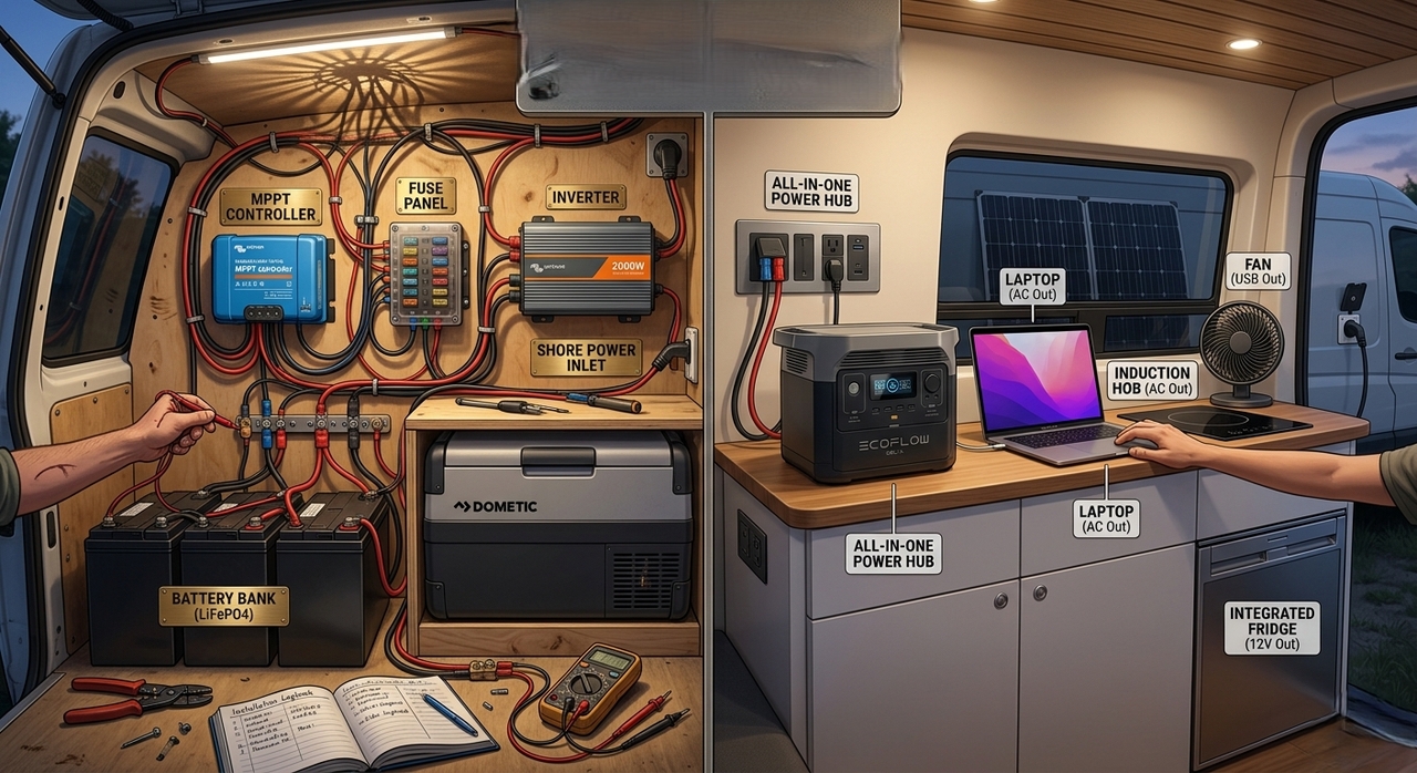
People feel they don't have the necessary qualifications. It's logical: The high-voltage AC system with a low-voltage DC system, running through the metal box on wheels, is a real risk. It's not like you're incapable if you're nervous. The problem is reframed in a systematic way, as demonstrated in Figure 1. You're not wiring a van, you're creating a series of steps that are logical. Input and output are well-specified for each step, and safety conditions are explicitly stated. Follow the flow from left to right, and all of a sudden, the complexity falls away and becomes manageable.
Why a Campervan Electrical Diagram Is Your Blueprint for Safety
A campervan electrical diagram reveals issues before they turn into physical dangers. A missing earth point is evident on paper. A cable run that is undersized will be apparent when it is rated with the amperage rating written on it. Also, there's a psychological benefit here, as working off a solid plan eliminates guesswork. If you're ever unsure whether a circuit is safe to trace, trace the line with your finger. Does it go through a fuse? Does the negative wire return cleanly to earth? The diagram provides an answer to both.
Mapping Out Your System Layout Before Buying Components
The biggest error in any van build is when there is a component mismatch. A 200W solar panel paired with a charge controller rated for 10A maximum, when the panel can output 11.5A at peak, will blow the controller on a bright August afternoon. Creating a paper layout will result in an accurate list of items to purchase. Start by cataloguing your daily power consumers: a 12V compressor fridge (480Wh/day on a 50% duty cycle), LED lighting (96Wh), a USB charging hub (54Wh), and a laptop (160Wh). Add all those numbers together, factor in 2 days of autonomy, and your battery bank minimum size becomes a number, not a guess.
Building From the Ground Up with a Self Build Campervan Electrics Diagram
Any self build campervan wiring diagram should take into consideration that there are two completely different electrical networks residing within the same metal shell: a 12V DC network for low-draw essentials, and an AC network for mains-voltage appliances.
Balancing Low-Voltage Essentials and High-Power Demands
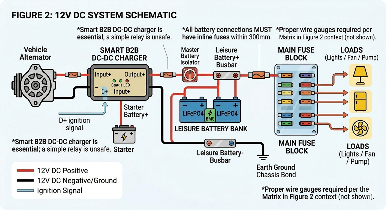
The water pump, the roof fan, and the LED strips are all powered by your 12V DC system. These are constant, low-draw loads that are directly connected from the leisure battery bank through a fused distribution block. Once you need to power a hairdryer, a microwave, or a laptop from a standard UK power socket, that's the AC territory, and an inverter is required. The location of these paths of divergence is shown in Figure 2 at the battery terminals, where two different paths spread out, and each is protected by its own fusing arrangement.
Integrating DC-to-DC Alternator Chargers Seamlessly
When you're driving, you are recharging your leisure bank as long as you've wired it correctly. You cannot have a straight link between your vehicle's starter battery and your leisure battery; it is genuinely dangerous. A flat leisure bank will drain the starter battery and leave you stranded. A smart B2B (battery-to-battery) DC-DC charger takes care of this problem. It reads the D+ ignition signal from the vehicle's alternator circuit and provides a controlled charge current only when the ignition (engine) is on. On your campervan electrics wiring diagram, this component is located between the starter battery positive terminal and the leisure bank positive terminal with a proper fuse in between each battery.
The Hidden Traps of Custom Campervan Electrical Wiring Diagram Designs
Poor crimps. Wrong cable gauges. Connections that rattle loose on a rough road on a B-road at 60mph. These are the failure modes nobody talks about. Even a 0.5V across an undersized cable run means your fridge compressor is working harder than it should and shortening its lifespan.
Wire Gauge vs. Amperage & Distance Reference Matrix:
The formula for calculating the cross-sectional area of copper is:
($$mm^2 = 2 \times 0.0175 \times L \times I \div 0.36$$)
At 3% maximum voltage drop for a 12V system, where L is the one-way distance from the power source to the device. Use flexible multi-strand automotive cable (ISO 6722 or FLRY-B), rigid household wire cracks from road vibration.
Cable Size (mm²) | Safe Continuous Current | Max One-Way Cable Run @ 3% VD | Typical Campervan Use |
1.0mm² | Up to 8A | 1.2m | LED lights, small 12V accessories |
2.5mm² | Up to 16A | 1.6m | Lighting circuits, USB hubs |
4.0mm² | Up to 25A | 1.6m | Water pump, roof fan |
6.0mm² | Up to 32A | 1.9m | Fridge compressor, MPPT to battery |
10mm² | Up to 50A | 2.0m | DC-DC charger output, fuse block feed |
16mm² | Up to 70A | 2.3m | Main battery to fuse block |
25mm² | Up to 100A | 2.5m | Battery to inverter (up to ~1,000W) |
35mm² | Up to 130A | 2.7m | Battery to inverter (1,000–1,500W) |
50mm² | Up to 170A | 3.0m | Battery to inverter (1,500–2,000W) |
Safe AC Integration and Your Campervan Electric Hook Up Diagram
Many DIY builds can be truly dangerous when it comes to shore power. A sound campervan electric hook up diagram treats 230V AC as a separate, fully isolated system that happens to share the same vehicle. It is not a system that is just bolted onto the existing 12V system.
Safely Wiring Shore Power for Campsite Connections
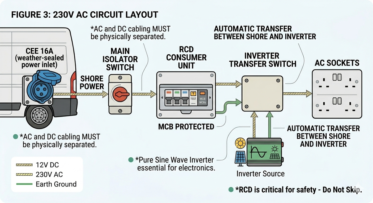
A standard, blue CEE 16A inlet is the entry point, located at a sensible height, and is weatherproof and lockable on the van exterior. Figure 3 traces the cable to a main isolator switch (which can also be seen from the inside), and then straight on to an RCD-protected consumer unit. The RCD (residual current device) cannot be avoided. It is used to check the voltage difference between live and neutral. It trips in milliseconds when that difference is greater than ~30mA (which means that something is faulty, or worse, someone is getting a shock). This setup ensures you can safely plug into campsite connections without risking a system fault.
Essential Rules for a Secure 240v Wiring Diagram for Campervan Power
A 240V wiring diagram for campervan wiring must physically separate AC and DC cabling. They run in different conduits, cable trays or at the very least different sides of the van's floor. AC cables should be double-insulated twin and earth cables, not the same spec as DC cables. The difference between a pure sine wave unit and a modified sine wave unit is huge on the inverter side. The modified sine wave unit is more affordable, but it will ruin sensitive electronic devices. Laptops, camera chargers, and medical devices all require a clean, pure sine wave output. Don't compromise here.
Fuses, Breakers, and Isolation Switches You Cannot Skip
A mega fuse or a class-T fuse within 300mm, ideally shorter, is required for each battery terminal. This is the last line of defence against a catastrophic short circuit. Your diagram callouts should explicitly mark these fuse positions as close to the battery positive terminal as physically possible. Add a master battery isolator, a rotary switch or a Tyco relay to shut off all power coming from outside the van in case of emergency. If there is no isolation switch, there won't be a safe build.
Eliminating Component Mismatch with a Comprehensive Campervan Electrical System Diagram
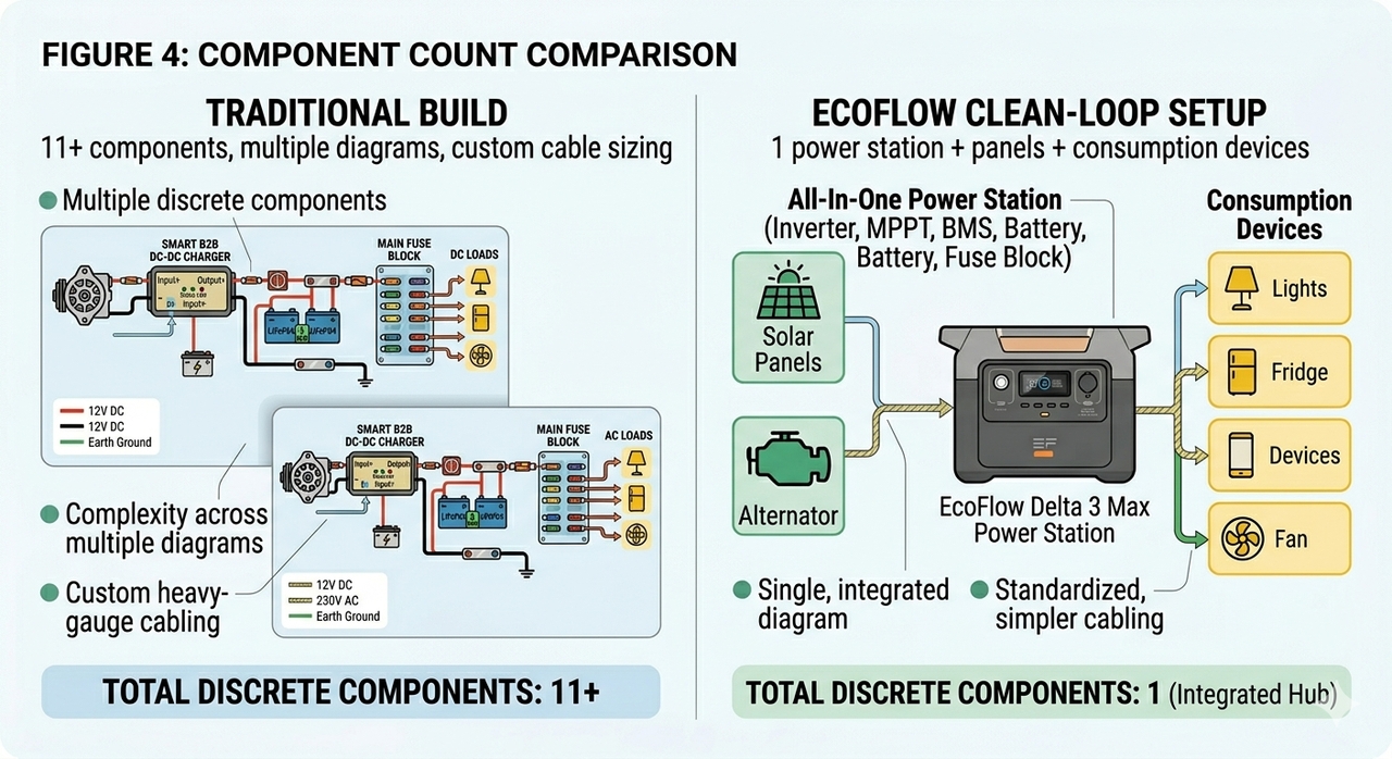
A campervan electrical system diagram for a traditional build lists somewhere between 11 and 15 discrete components: panels, MPPT controller, busbar, leisure batteries, BMS, DC-DC charger, fuse block, inverter/charger, RCD unit, transfer switch, and AC sockets. They all need to be properly sized to fit, have appropriate connectors, and be positioned properly.
Calculating Daily Power Budgets Without Overcomplicating the Math
Sample Power Estimation Worksheet:
Below is a fridge figure based on a 60W compressor with a duty cycle of 33% (8 hours per day). All the other figures are related to the average real-world usage. In each case, check the data plate of your particular appliances and apply a 25% headroom for battery degradation.
Appliance | Wattage | Daily Run Time | Daily Wh |
12V Compressor Fridge (50L) | 60W (when running) | 8h duty cycle | 480Wh |
LED Lighting (6 × 4W fittings) | 24W total | 4h | 96Wh |
Roof Fan | 5W (high speed) | 8h | 40Wh |
Laptop (via 12V charger) | 80W | 2h | 160Wh |
Phone/USB Charging (×2) | 18W | 3h | 54Wh |
Water Pump (intermittent) | 10W | 0.5h | 5Wh |
Total | 835Wh/day |
With two days' autonomy and LiFePO4 cells (safely dischargeable to 80%), you need a bank rated at roughly 2,100Wh (175Ah at 12V). Round up to the nearest standard size, 200Ah.
Sizing Your Solar Array and MPPT Charge Controller Safely
Two 200W panels wired in series double the voltage; wired in parallel, they double the current. Under partial shade conditions, series wiring is suitable for MPPT controllers that have a greater tolerance for voltage. Parallel wiring maintains a lower voltage, yet requires larger-sized wire. Neither is better overall; you will have to determine based on your roof space, controller spec and shading situation. Map this on your campervan electric diagram before drilling a single roof penetration.
Switching to All-In-One Power Stations to Eliminate Wiring Chaos
Figure 4 tells the story plainly. In an integrated power station, the inverter, MPPT controller, BMS, battery cells and AC/DC distribution are all integrated onto a single chassis. A multiple-power-station-to-power-camperloop reduces the campervan electrical diagram to a one-clean-loop: panels to power station input to power station output to appliances. No busbar calculations. No charge controller compatibility research. No custom cable sizing between components that weren't designed to talk to each other.
Simplifying Your Setup with EcoFlow Delta Portable Power Stations
EcoFlow's Delta range is engineered specifically for the scenario described in Figure 4, replacing a tangled multi-component diagram with a single, road-hardened hub that manages all power flows internally.
Streamlining Your Core Blueprint with the EcoFlow DELTA 3 Series Portable Power Station
Adding the EcoFlow DELTA 3 Series Portable Power Station into your campervan electrics diagram condenses the following four major components into a single box:
The solar charge controller
Battery bank
Inverter
Battery management system
The Delta 3 series portable power station can cover your daily needs if you have a power budget that matches our baseline worksheet for running standard 12V essentials, such as fridge, lights, and fans. The benefit this unit offers you is that you don’t need to sketch out confusing inter-component fuses or heavy busbar connections. Instead, the layout simplifies into clean lines showing direct solar input and straightforward AC or DC distribution to your appliances.
Scaling Your Schematic for Heavy Loads with the EcoFlow DELTA 3 Max Series Portable Power Station
If your campervan has heavy duty appliances, such as induction hobs, microwaves, or hair dryers, the EcoFlow DELTA 3 Max Series Portable Power Station is the solution you need. Running a traditional DIY setup requires you to rewrite your wiring map with thicker cable gauges, massive fuses, and dedicated distribution blocks, to scale up the power demand. Implementing an all-in-one hub, like the Delta 3 Max helps you bypass this headache because the core wiring path on your paper blueprint remains completely unchanged. This means that you retain the exact same clean, plug-and-play layout while gaining the massive energy reserves and output capacity required to run high-wattage mains gear safely.
Conclusion
Building a safe off-grid system starts not with a crimping tool, but with a pencil and a clear campervan electrics diagram. In this guide, we have covered everything, including a simplified energy flow chart in Figure 1, to the full AC integration rules in Figure 3. Understanding these components is what makes a safe, functional build from a fire hazard on wheels. Whatever your approach to shore power routing is, whether it be using the RCD consumer unit, using the RCD cable size matrix or calculating out how many Wh you need for each day from scratch, the principle is always to plan first, make the connection second.
The traditional, multi-component approach can seem more complicated than rewarding, and EcoFlow's Delta series allows for a legitimate engineering trick, not a compromise. At EcoFlow, the DELTA 3 and DELTA 3 Max power stations replace the most diagram-intensive sections of any van build with a single, pre-engineered unit. Explore the full range and find the power station that fits your build. Your wiring diagram will thank you for it.
Campervan Electrics Diagram Frequently Asked Questions
Q1: What thickness of wire do I need for my campervan electrics wiring diagram?
The wire's thickness is completely determined by current (amperage) and the length of the cable run. A small wiring will cause resistance, voltage drop, and fire. Follow the instructions in this guide using the gauge matrix as a starting point, or select an integrated power station hub to bypass custom cable calculations entirely.
Q2: Can I combine a 240V mains hookup and solar power in the same campervan electrics diagram?
Yes. A good layout is one that takes into consideration many sources of input simultaneously. Traditional builds will need a mains battery charger and a solar MPPT controller with their own set of wiring. The flows are simplified to allow the EcoFlow Delta stations to take in campsite shore power as well as solar array input at the same time.
Q3: Do I need a grounding point in a self build campervan wiring diagram?
Absolutely. Your 12V DC negative system and your 240V AC safety earth must both bond directly to the bare metal van chassis. This guarantees a safe fault path if a short circuit occurs anywhere in the living space, and it must be shown explicitly on your diagram, not assumed.